Kalıp akış analiz raporu nedir?
Kalıp Akış Analizi (MFA), enjeksiyon kalıplama işlemi sırasında bir kalıptaki plastik reçinenin akışını tahmin etmek ve optimize etmek için kullanılan bir simülasyon aracıdır. Simülasyon, reçinenin özelliklerini ve kalıbın geometrisini hesaba katar ve plastiğin kalıbı doldururken ve soğurken davranışını tahmin eder.
Kalıp Akış Analizi raporu Enjeksiyon kalıplama sürecinde oluşan kısa paslar, eğilme, kaynak çizgileri, hava hapsi, çökme izleri vb. gibi potansiyel sorunların belirlenmesine ve çözülmesine yardımcı olabilir. Kalıp Akış Analizi raporu Ayrıca, kapılar ve koşucular için en iyi konumu belirleyerek, optimum enjeksiyon hızını belirleyerek ve en iyi soğutma süresini ve sıcaklığını tahmin ederek enjeksiyon kalıplama sürecini optimize etmek için de kullanılabilir. Bu, çevrim süresini azaltmaya, parça kalitesini iyileştirmeye ve üretim verimliliğini artırmaya yardımcı olabilir.

Kalıp akış analiz raporu
Kalıp Akış Analizi Sonuçları Özeti
Kalıp tasarımını bitirdiğimizde, kalıp imalatına başlamadan önce, her şeyin sorunsuz olduğundan emin olmak için, şunları yapmamız gerekir: kalıp akış analizi Olası sorunları kontrol etmek, özellikle büyük kalıplar için hatalardan kaçınmanın güvenli bir yoludur. Aşağıda kalıp akış analizi raporu hazırlarken kontrol etmemiz gereken bazı noktalar bulunmaktadır.
Kalıp Doldurma Süresi – Doldurma süresi, parça boşluğunu doldurmak için gereken süredir. Doldurma süresi grafiği ayrıca kalıp boşluğunun doldurulmasının bir animasyonunu da sağlar. Doldurma süresi, yüksek kesme gerilmeleri gibi kalite sorunlarını çözmek için analiz sırasında da kontrol edilebilir.
Enjeksiyon Basıncı – A standard injection molding machine is capable of pressurizing the melt flow to 20,000 psi (2,000 psi hydraulic gage pressure). A portion of the pressure is used to push the plastic through the runner system, some of the pressure is used to push the plastic into the kalıp boşluğu, and a portion of the pressure is used to “pack out” the part after it is filled. If the part and runner system require more pressure than the machine is capable, than the part will be a short shot or have deep batma izleri.
Kaynak Hatları Kusurlar – Weld lines are formed when two flow fronts meet and “weld” together. Weld lines are usually a visible line on the part and can be an appearance issue. Weld lines may also reduce the part strength by 10% – 20% potentially creating a structural issue depending on their location. If mold flow analysis is not used to fix these problems before the tool is built, the molder will be forced to: increase injection pressure, increase melt temperature, increase mold temperature, enlarge vents, change the gate location and/or alter the thickness of the part. All of these “solutions” take time and money to implement and/or increase the cost of the part.
Hava Tuzakları Kusurlar – Air traps are formed when the molten plastic traps air in the part cavity as it fills. If these air traps are not vented, they can lead to quality problems such as burn marks, short shots, pronounced weld lines and incomplete fill. Our air trap plots allow the toolmaker to know exactly where the vents need to be placed when the tool is built. Air traps that are in locations that are difficult to vent can be moved to better locations by moving the gate. Doing this work before the tool is built can save on the amount of debug and mold changes that are required.
Kalite – The definition of a quality molded part is not only that the part filled completely. A quality molded part must also be free of material degradation and low in molded in stress. The quality plot shows the severity and areas that are suffering from quality problems. The problems detected include excessive shear stress and shear rate, and hard to pack areas. Suggestions like thickness adjustments, processing condition changes and fill time adjustments can be tried to eliminate the quality issues.
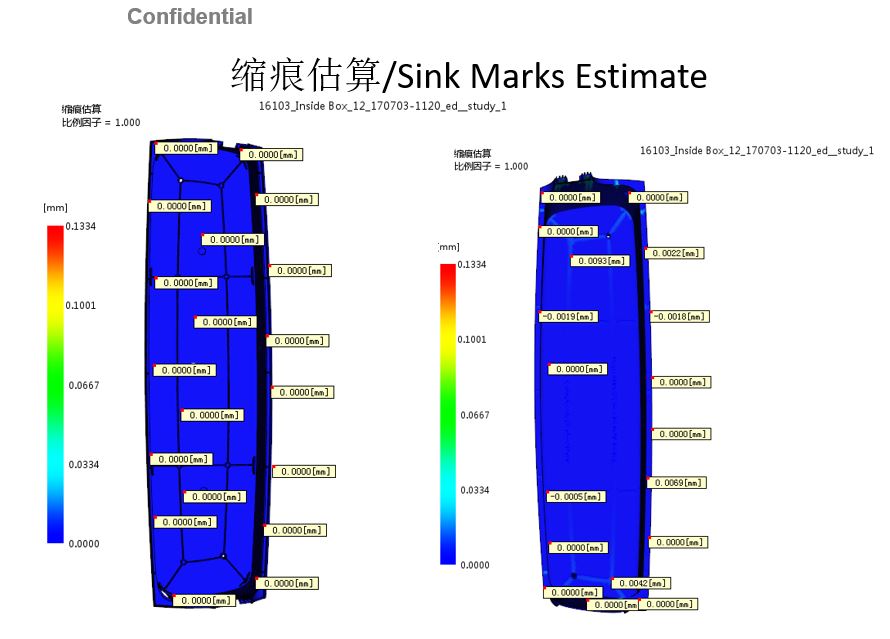
Çökme izleri Kusurlar – Sink marks are localized depressions in the surface of injection molded parts caused by a non uniform shrinking of the plastic during the cooling. In cosmetically critical parts, they can be a serious problem. Sink marks often come as a surprise when the tool is complete. If the sink marks are objectionable to the customer, the molder is often tasked with “eliminating them”. This usually means running the molding machine at the extremes of the process window, which can lengthen cycle times and increase the amount of molded in stresses and material degrade.
Soğutma Süresi – It has been shown that cooling time averages about 50% of the molding cycle. If the material in use is a commodity resin, the molding cost far outweighs the material cost. In this case, a reduction in cooling time has a big reduction in the part cost. Our Cooling Analysis can reduce your cooling cycle and optimize your cooling system eliminate hot spots and warpage.
MFA, plastik reçinenin kalıptan akarken ve soğurken davranışını simüle ederek enjeksiyon kalıplama sürecinin verimliliğini ve kalitesini iyileştirmeye yardımcı olabilen güçlü bir araçtır. Potansiyel sorunları belirlemeye ve kusurları en aza indirmek ve nihai ürün kalitesini iyileştirmek için süreci optimize etmeye yardımcı olur.
Projeniz için kalıp akış analizi yapıyoruz
Çok fazla endişe duyduğunuz bir projeniz varsa lütfen bizimle iletişime geçin, tüm parça çizimlerinizi kontrol edip, DFM raporu Ve kalıp akışı Sizin için analizler hazırlayıp, olası tüm sorunları veri sayfasında özetleyip size geri gönderiyoruz.

