Schlagwortarchiv für: 3-Platten-Spritzgussform

Zwei-Platten-Spritzgussform

Was ist eine Zweiplatten-Spritzgussform?

Zwei-Platten-Spritzgussform (2-Platten-Spritzgussform), 3-Platten-Spritzgussform und alle anderen Arten von Kunststoff-Spritzgussformen sind Formentypen, die beim Kunststoff-Spritzguss verwendet werden, in 2-Platten-Formen, in denen zwei separate Formplatten verwendet werden, um den Formhohlraum zu bilden, eine Platte, die wir „A“-Platte oder A-Taschenplatte nennen, die den Hohlraum und die feste Hälfte enthält, und normalerweise nennen wir dies Hohlraumseite, die andere Platte ist „B“-Platte (oder Kernseite/bewegliche Seite), die Kerneinsätze enthält, die die bewegliche Hälfte sind, das Auswerfersystem befindet sich ebenfalls auf der Kernseite.

Der Kunststoff wird durch den Anguss in die Formhöhle eingespritzt, und dann wird die B-Platte gegen die A-Platte geschlossen, um das Teil zu formen. Sobald der Kunststoff abgekühlt und verfestigt ist, wird die B-Platte geöffnet und das Teil ausgeworfen. Diese Art von Form wird im Allgemeinen für kleinere, einfachere Teile mit minimalen Hinterschneidungen oder komplexen Geometrien verwendet.

Vorteile der Zweiplattenform

Zwei-Platten-Spritzgussform

Zwei-Platten-Spritzgussform

Das Schöne am Zweiplatten-Design ist seine Einfachheit. Dies bringt mehrere Vorteile mit sich:

  • Kostengünstig: Mit weniger Teilen und einem unkomplizierten Design sind Zweiplattenformen die wirtschaftlichste Option. Daher empfiehlt sich die Zweiplatten-Spritzgussform für die Massenproduktion weniger komplexer Teile.
  • Einfache Wartung: Aufgrund ihrer einfachen Konstruktion sind Zweiplattenformen einfacher zu warten und zu reparieren.
  • Schnelle Zykluszeiten: Der einfache Öffnungs- und Schließmechanismus ermöglicht schnellere Produktionszyklen im Vergleich zu komplexeren Formen.
  • Geeignet für eine Vielzahl von Materialien: Sie können eine Vielzahl von Thermoplasten verarbeiten und sind daher vielseitig für verschiedene Anwendungen geeignet.

Nachteile des Zweiplatten-Spritzgusses

Zweiplattenformen bieten zwar zahlreiche Vorteile, haben jedoch auch Einschränkungen:

  • Ästhetik der Angussmarkierung: Die Stelle, an der der geschmolzene Kunststoff in die Kavität eintritt (die Angussmarkierung), kann auf dem Endprodukt eine sichtbare Markierung hinterlassen.
  • Komplexität der Teile: Sie haben Probleme mit Teilen, die Hinterschneidungen, tiefe Kerne oder Gewinde aufweisen. Diese Merkmale erfordern zusätzliche Mechanismen, die die Komplexität und die Kosten erhöhen.
  • Angussabfall: Das am Formteil befestigte Angusssystem muss entfernt werden, wodurch Kunststoffabfall entsteht.

Der Formprozess in Aktion

Die Spritzgussform mit zwei Platten durchläuft einen präzisen Zyklus zur Herstellung von Kunststoffteilen. Hier ist eine vereinfachte Aufschlüsselung:

  1. Klemmen: Dabei werden B-Seite und A-Seite durch Anwendung eines hohen Drucks fest miteinander verbunden, wodurch eine perfekte Abdichtung gewährleistet wird.
  2. Einspritzen: Der geschmolzene Kunststoff wird unter hohem Druck durch das dafür vorgesehene Teil oder den Anguss in die Formhöhle eingespritzt.
  3. Verdichten und Halten: Nach dem Füllen der Kavität wird der Druck aufrechterhalten, um die Schrumpfung des Kunststoffs während der Abkühlung auszugleichen.
  4. Kühlung: Um das Kunststoffteil zu verfestigen, wird die Form mit Wasserkanälen gekühlt.
  5. Formöffnung: Die B-Seite zieht sich zurück und erzeugt eine Trennlinie, an der sich die beiden Formhälften trennen.
  6. Auswerfen: Stifte oder andere Mechanismen drücken das fertige Kunststoffteil aus der Kavität.
  7. Entfernen des Angusskanals: Der übrig gebliebene Kunststoff aus Anguss und Kanälen (Angusskanal genannt) muss möglicherweise manuell vom Teil entfernt werden.

Unterschied zwischen Zweiplatten- und Dreiplattenform

Eine Zwei-Platten-Form und eine Drei-Platten-Form Beim Kunststoff-Spritzguss werden unterschiedliche Formen verwendet. Der Hauptunterschied besteht in der Anzahl der Platten, die zur Bildung der Formhohlräume verwendet werden.

Zwei Plattenformen:

Stellen Sie sich eine Muschelschale vor. Dies ist das grundlegende Konzept einer 2-Platten-Spritzgussform. Diese besteht aus zwei Hauptkomponenten. Erstens die feste Platte oder auch „A-Seite“ genannt und zweitens die bewegliche Platte oder „B-Seite“.

Die Magie geschieht innerhalb dieser beiden Hälften. Die A-Seite enthält einen Hohlraum, der die gewünschte Form des endgültigen Kunststoffteils nachbildet. Die B-Seite kann einen Kern haben, der interne Merkmale bildet oder einfach als Gegenstück zum Hohlraum fungiert. Diese beiden Seiten kommen zusammen und bilden einen abgedichteten Behälter, in den geschmolzener Kunststoff eingespritzt wird.

  • haben zwei separate Formplatten, die „A“-Platte und die „B“-Platte.
  • Die A-Platte enthält die Kavität und den Kern, und die B-Platte enthält den Auswerfermechanismus.
  • Der Kunststoff wird durch den Anguss in die Formhöhle eingespritzt und dann wird die Platte B gegen die Platte A geschlossen, um das Teil zu formen.
  • Sobald der Kunststoff abgekühlt und fest geworden ist, wird die Platte B geöffnet und das Teil ausgeworfen.
  • Dieser Formtyp wird im Allgemeinen für kleinere, einfachere Teile mit minimalen Hinterschneidungen oder komplexen Geometrien verwendet.

Drei Plattenformen:

  • haben drei separate Formplatten, die „A“-Platte, die „B“-Platte und die „C“-Platte (oder Angussplatte).
  • Die Platte A enthält die Kavität, die Platte B den Kern und die Platte C den Angusskanal, den Angusskanalschieber mit Auswerfer auf der Kavitätsseite (dieser Auswerfer wirft nur den Angusskanal aus, den wir auch Angusskanalschieber nennen).
  • Der Kunststoff wird durch die C-Platte (Angussplatte) in die Formhöhle eingespritzt. Anschließend wird die B-Platte gegen die A-Platte geschlossen, um das Teil zu formen.
  • Sobald der Kunststoff abgekühlt und ausgehärtet ist, wird die C-Platte geöffnet, um den Angussstab mit der C-Platte herauszuziehen und dann den Anguss mit einem Drücker von der Angussplatte auszuwerfen. Anschließend wird die B-Platte geöffnet und das Teil ausgeworfen.
  • Dieser Formtyp wird im Allgemeinen für größere, komplexere Teile mit Hinterschneidungen oder anderen Merkmalen verwendet, die mit einer Zweiplatten-Spritzgussform nicht hergestellt werden können.
3-Platten-Form vs. 2-Platten-Form

3-Platten-Form vs. 2-Platten-Form

Zusammenfassend lässt sich sagen, dass der Hauptunterschied zwischen Zweiplatten- und Dreiplattenformen darin besteht, dass sich bei Zweiplattenformen der Angusskanal auf der A- oder B-Platte befindet, die sich auf der Trennlinienebene befindet, und durch das Auswerfersystem teilweise ausgeworfen wird, während bei Dreiplattenformen der Angusskanal an der C-Platte (Angussplatte) klebt und später durch den Drücker ausgeworfen wird. Diese Formen sind komplexer und teurer als Zweiplattenformen.

Haben Sie ein Projekt, bei dem Kunststoff benötigt wird? Formenlieferanten? Bitte kontaktieren Sie uns, um ein Angebot zu erhalten. Wir sind in der Lage, 2- oder 3-Platten-Spritzgussformen herzustellen.

Drei-Platten-Kaltkanalform

What is 3 plate injection mold

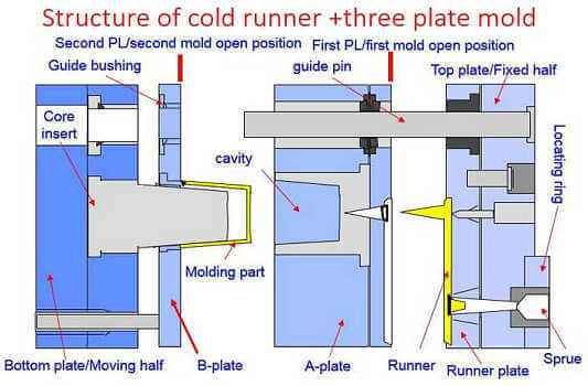
3-Platten-Spritzgussform (three plate injection mold), also known as a triple plate mold, is a specialized type of injection mold that is used to produce parts with by cold sub runner mold structure. A 3-Platten-Spritzgussform is made up of three separate plates – the core plate(B plate), the cavity plate (A plate), and the runner plate (C plate). The core plate is located on the moving side of the mold, while the cavity plate is on the stationary side. The runner plate is located on the back of the cavity plate and is used to eject the runner when mold open.

In traditional injection molding, a 2 plate injection mold is used to create a part, when the 2 plate mold is not possible to make this part, for example the gate mark need to place on the top of part but need to use cold runner, and need good surface, or need fill more balance in case sometimes the size is big. then three plate injection mold maybe the better idea to solve this issue.

A 3-Platten-Spritzgussform, on the other hand, utilizes three separate plates to create a single part with multiple colors or materials. The first plate (A plate), known as the cavity plate, contains the mold cavities for the main part. The second plate (B plate) , known as the core plate (core pocket plate), contains the mold cores. The third plate (C plate), known as the runner plate, contains the push pins that are used to push the runner during the molding. Below are A,B,C plate of their roles:

A Plate (Cavity Plate): Forming Precision in the Mold

The A plate, now designated as the cavity plate or cavity pocket plate, holds the cavity insert and fasten in the pocket in the 3 plate injection mold. this is same to 2 plate injection mold which will have cooling pipe in it. Here are key aspects of the A plate as the cavity plate:

  1. Cavity Formation: The A plate is the canvas where the actual shape and features of the plastic part are molded. It houses the negative impression of the desired product, defining the cavity into which molten plastic will be injected.
  2. Mold Base Stability: As the cavity plate, the A plate forms the stable base of the mold assembly. Its robust construction, often crafted from durable steel materials like S50C or P20, provides the necessary stability to withstand the pressures and forces exerted during the injection molding process.
  3. Sprue and Runner System Integration: The A plate typically incorporates the sprue, the main channel through which molten plastic is injected into the mold. Additionally, elements of the runner system, which guides the plastic flow from the injection unit to the mold cavity, may be part of the A plate’s design. 3 plate injection mold normally has complex runner design than 2 plate injection mold, because there will be some of runner located at back side of A plate, so that C plate (runner plate) can pull the runner away from the forming part.
  4. Parting Line Definition: The interface between the A plate and the B plate forms the parting line, a critical boundary that defines how the mold separates to reveal the molded part. The seamless definition of the parting line is crucial for achieving a flawless final product. 3 plate injection mold will normally have 2 parting line, this parting line is between A plate and B plate (cavity and core). see below picture.
3-Platten-Spritzgussform

3-Platten-Spritzgussform

B Plate (Core Plate / B Pocket Plate): Shaping the Heart of Precision

In the symphony of the 3 plate injection mold, the B plate takes on the role of the core plate (Core pocket pate), a dynamic element responsible for shaping the very essence of the molded product. Designated as the B pocket plate, it not only accommodates the core insert but also serves as the stage where precision is meticulously crafted. Here are key aspects of the B plate as the core plate:

  1. Core Insert Integration: The B plate is designed to house the core insert, which defines the internal features and contours of the molded part. This insert complements the cavity created in the A plate, collectively forming the complete mold impression.
  2. Parting Line Definition: Collaborating with the A plate, the B plate contributes to defining the parting line, a critical boundary that separates the mold’s halves. The seamless interaction between these plates ensures a smooth transition during the mold opening and closing phases.
  3. Runner System Components: The B plate may contain elements of the runner system, including channels that guide the flow of molten plastic from the injection unit to the mold cavity. This separation of the runner system from the molded part is a hallmark of the 3 plate injection mold design. But if the gate directly feed to the molding part from C plate, then there will be no any runner at B plate.
  4. Ejector Pin Interaction: Ejector pins from the ejector plates are strategically placed to interact with the B plate. These pins are instrumental in the ejection phase, applying force to the B plate and subsequently ejecting the solidified plastic part from the mold.

The B plate, as the core plate or B pocket plate, plays a central role in shaping the heart of precision within a 3 plate injection mold.

Three plastic injection mold


C Plate (Runner Plate): Navigating the Path to Seamless Separation

In the choreography of a 3 plate injection mold, the C plate gracefully steps into the role of the runner plate, positioned strategically near the top fixed plate. With precision and purpose, it orchestrates the separation of the molded part and the runner, ensuring a seamless and efficient molding process. Here are key aspects of the C plate as the runner plate:

  1. Runner Management: The C plate takes charge of the runner, which is the channel through which molten plastic flows from the injection unit to the mold cavity. Its proximity to the top fixed plate allows it to efficiently pull the runner away from the A plate (separate the molded part and runner), preventing entanglement with the molded part.
  2. Top Fixed Plate Interaction: The C plate operates in close proximity to the top fixed plate, collaborating to create a controlled environment for separating the runner and the molded part, plus there will be pull pins assembled on top plate which will go through to A plate, those pull pins is the critical function to pull the runner away from A plate. This cooperative movement is essential for the overall efficiency of the mold.
  3. Runner Cooling Considerations: As the runner plate, considerations for efficient cooling may be incorporated into the C plate’s design. Proper cooling helps manage temperature differentials and contributes to the overall quality of the molded parts. normally there will be no any cooling channel needed on the C plate, but for some complex part or big part may need additional cooling line on the C plate.

Three plate injection molding working steps

sub-runner 3 plate mold

sub-runner 3 plate mold

In the 3 plate injection mold, the sub-runner travels along a second parting line other than the primary parting line where the part is formed. The two parting lines are normally parallel to each other and are separated, and partially defined, by at least one mold plate. The sub-runner and part forming cavities are connected by an extension of the sub-runner referred to as a secondary sprue. The bridging secondary sprue passes though the at least one separating mold plate and connects to the part-forming cavity through a small gate opening. The secondary sprues are normally parallel to the opening direction of the mold and perpendicular to the sub-runner (see Fig. 1.2).

During molding, after the plastic melt in the runner and part forming cavity solidify, the mold will open along the two parting lines. The part is ejected from the opened primary parting line and the runner (which includes the secondary sprue and gate) is ejected from the opened second parting line as seen in Figure 1.3.

3-plate injection mold

3-plate injection mold

Das three plate injection mold is commonly referred to as a three-plate cold runner mold. The terms two-plate and three-plate cold runner molds refer to the minimum number of mold plates required to form and to allow removal of both the part and the solidified runner. With the two-plate cold runner mold, the part and runner are formed and removed between at least a first and second mold plate. With the three-plate cold runner mold, the part is formed and removed between at least a first and second plate and the runner and gate are formed and removed between at least a third plate and often the same second plate used to help form the part.

This type of mold is used when it is desirable to gate the part in a location other than the perimeter. It is commonly used for molding gears where it is desirable to gate in the center hub of the gear.

One of the advantages of using a 3-plate injection mold is that it allows for big size of part, using 2 plate mold may not able to fill completely, then use 3 plate injection mold can solve this issue very easy, the 3-plate design allows for better control of the flow of molten material during the injection molding process, resulting in a higher-quality finished product.

However, there are also some disadvantages to using a 3-plate injection mold. One disadvantage is that it can be more expensive to produce than other types of injection molds. This is because the three-plate mold structure is more complex so that the moldbase will be higher than two plate injection mold.

Another disadvantage of 3 plate injection molding is that it can be more time-consuming to produce than other types of injection molds. Because the sub-runner so that need manual or robot to pick up the sub-runner every molding shot, so the cycle time will be longer and the material waste will be more higher.

Despite its many benefits, 3-Platten-Spritzgussform is not always the right solution for every application. The specialized equipment and expertise required to produce parts using this method can make it more expensive than traditional injection molding. It is also not well suited to high volume production runs ( hot runner will be better), as the cost and complexity of the 3-plate mold may not be justified for small production quantities.

When it comes to deciding whether to use a 3 plate injection mold, 2 plate injection mold or Heißkanalform, , it is important to consider the specific requirements of the project. For example, if the final product requires a high degree of precision and quality, then a 3-plate injection mold may be the best option. Additionally, if the final product requires better surface and well filling status, or have big part size, then use 3 plate plastic injection mold.

Finally 3 plate mold and 2 plate plastic injection mold are using for different type of parts, this is depending on the part surface, part size, if you have a project that need plastic mold service, contact us to get a price.

If you have any project that needs custom plastic injection molds, welcome to contact for quote.