Brass insert moulding

What means brass inserts for plastic injection molding

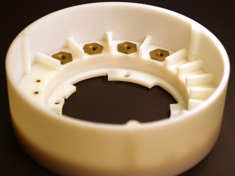
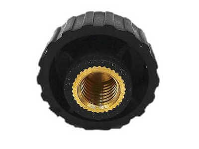
Brass inserts for plastic injection molding are small metal components that are used in injection molding process to create a wide variety of parts and products, this process we call insert molding process. These inserts are typically made from brass, a strong and durable metal that is resistant to corrosion and wear. They are used in a range of industries, including automotive, medical, and consumer products.

Injection molding is a manufacturing process that involves injecting molten material, such as plastic or metal, into a mold to produce parts and products. During the injection molding process, the brass inserts are placed into the mold, and the plastic is injected around them. The mold is then cooled, and the finished part is ejected from the mold.

Advantages of brass inserts for injection molding

brass inserts for plastic injection molding

There are a few key benefits to using brass inserts in plastic injection molding:

  • Strength: Brass is a strong and durable metal that is resistant to impact and wear. When used as inserts in plastic injection molding, brass can help to increase the strength and durability of the finished part.
  • Corrosion resistance: Brass is resistant to corrosion, making it a good choice for parts that will be exposed to harsh environments or chemicals. This can help to increase the lifespan of the finished part and reduce the need for maintenance or repairs.
  • Wear resistance: Brass has good wear resistance, making it a good choice for parts that will be subjected to high levels of wear or friction.
  • Customization: Brass inserts can be customized to a wide range of shapes and sizes, making them suitable for a range of applications. They can also be modified with coatings or other treatments to achieve specific properties, such as increased corrosion resistance or improved wear resistance.
  • Ease of use: Brass inserts are easy to install and remove, making them convenient for use in the injection molding process. They can be placed into the mold quickly and easily, and they can be removed from the finished part just as easily.
  • Cost-effectiveness: Brass inserts are generally less expensive than other materials used in injection molding, such as stainless steel or aluminum, making them a cost-effective choice for many manufacturers.

Factors to consider when using brass inserts in plastic injection molding There are a few key factors to consider when using brass inserts in plastic injection molding:

  • Compatibility with the plastic: It’s important to ensure that the brass inserts are compatible with the plastic being used in the injection molding process. Different plastics may have different properties and requirements, and it’s important to choose brass inserts that can be used effectively with the chosen plastic.
  • Compatibility with the injection molding machine: It’s important to ensure that the brass inserts are compatible with the injection molding machine that will be used for the project. Different machines may have different capabilities, and it’s important to choose brass inserts that can be processed effectively by the machine.
  • Required properties of the finished part: The properties of the finished part, such as strength, stiffness, and corrosion resistance, will depend on the specific grade of brass being used. It’s important to choose the right grade of brass for your application to ensure that the finished part has the desired properties.
  • Cost: The cost of the brass inserts is an important factor to consider, as it can have a significant impact on the overall cost of the project.
  • Availability: It’s important to ensure that the brass inserts you need are readily available, as delays in material delivery can impact the timeline of your project.
  • Sustainability: If sustainability is a concern, it may be worth considering brass inserts made from recycled materials.

In conclusion, brass inserts are a popular choice for use in plastic injection molding due to their strength, corrosion resistance, wear resistance, customization, ease of use, and cost-effectiveness. When using brass inserts in plastic injection molding, it’s important to consider factors such as compatibility with the plastic and the injection molding machine, the required properties of the finished part, cost, availability, and sustainability. By carefully considering these factors, you can choose the best brass inserts for your injection molding project and ensure the success of your project.

long run plastic injection molding

When the requirements for polymer parts go beyond 3D printing and machining, it is recommended that product engineers should turn to injection molding. Conventional injection molding entails identifying the right tooling vendor and then buying the tooling, which may take several months. It may take a long time and is very tiresome, but the cost per unit is relatively low, especially when making many pieces of the items. Fortunately, there is an alternative: short run plastic injection molding.

Comprehension Short Run Plastic Injection Molding

When there is a small production of the product, short-run injection molding employs cheaper tools as compared to long-run injection molding (or high volume injection molding). This process also does away with the conventional high-volume manufacturing system that requires much rigidity, long cycle time and large capital investment. However, in this case, short-run injection molding is more appropriate in the short run than in the long run.

The temporary molds are of aluminum while the ‘hard’ production tools are of cemented tool steel. This metal is characterized by high thermal conductivity and good workability. Aluminum molds are slightly less rigid than steel molds, but they are the most suitable for runs of less than 10,000 pieces. In addition, they are cheaper than steel molds and the final parts are made in weeks, not in months, as is in the case of steel molds.

Short run injection molding is the most appropriate for any organization that needs quality plastic parts at an affordable price and within a short time.

short run plastic injection molding

Benefits of Short Run Injection Molding

The benefits of short-run injection molding are as follows:

Aluminium injection moulds are cheaper as compared to reinforced steel moulds that are available in the market today. The degree of savings is dependent on the number of cavities, the geometry of the part and the moulding issues like undercuts or inserts. However, the difference in costs is normally quite large.

But this is not the only advantage that can be derived from this, the cost factor has to be considered. The ability to make changes and the short cycle times can thus be helpful in cutting down the time taken to develop products hence, cutting down the time to market. However, unlike most organizations, our short-run injection molding service does not bind the customers to order in large quantities. They are made from materials of production-grade and have adequate surface finishes that can be used.

Short Run Injection Molded Costs For Parts Production

It is also important to note that the cost of manufacturing the short run injection mold for fabricating small quantity products and setting up is fixed and has to be spread over the number of orders.

Generally, short run injection molding is appropriate for parts ranging from 1 to 10,000. At Sincere Tech, we provide two tooling options: prototype molds, which are normally associated with a warranty of at least 2000 shots and on-demand production molds, which are associated with a mold life warranty. If the aluminum tool is spoilt, then the company will replace it without charging the customer anything. Regarding the quantity of the produced product, both options are fairly inexpensive.

Other special services are first article inspection, capability reports, scientific molding process development reports and PPAP. Some clients have realized that a short-run aluminum mold can be used as the end product mold.

If the volumes are in the millions, then production tooling might be more appropriate. On the other hand, 3D printing can be cheaper in the instance of manufacturing a few numbers of parts. Some of the manufacturers use 3D printing to create the prototypes and then use small run injection molding.

Uses of Short Run Injection Moulding

The best strategy is relative to the needs of the organization and the situation in the organization. For example, a medical device manufacturing firm that has developed a new medical device but is in doubt about the market situation can use a short-run injection instrument. This is in favor of a “pay-as-you-go” approach during the product’s introduction. If, at some later date, they decide to invest in a steel tool, the aluminum mold can be used as an interim tool up to the time the production mold is made.

It is also significant to note that bridge tools are not limited to the ramp-up stage of the product introduction only. They can be a fairly cheap way to have an insurance policy for mature programs. For instance, an appliance manufacturer was in a position to proceed with the production process since he or she utilized a bridge tool to fix the main tool. They now have an extra mold that they can use in the future, for instance, if the demand for the product rises or if the current tool is not effective.

The short-run injection molding is a good middle ground for the designers to get the best mold design and the performance of the final product with relatively low risk as compared to the direct use of steel production tools from the 3D printed models. This is more so in industries such as medical devices where it is important to shorten the time it takes to develop these products while at the same time ensuring that the products meet the set regulatory standards since this is cost-effective.

plastic injection mold tooling

High-volume injection molding

Our digital network is capable of producing larger and more intricate parts in high volume in case short run injection molding is not applicable to your case. Our expandable range of services includes;

  • Projects for molded elements that are large, heavy and elaborate in design
  • Quotes for more than 100,000 components
  • Molding capabilities for parts that are up to 79 inches (2 meters) in size
  • Mold-Tech finishes and a variety of surface finishes (A1-A3, B1-B3, C1-C3, D1-D3).
  • Toolings like Tool Steel P20 and Aluminium & Steel, color matching Tooling as per the requirement of the customer.
  • Would you like to know more about short run injection molding? Upload a file for a free mouldability check and then speak with a member of the Protolabs molding team. Start the fast and effective production of parts with our services.

Is the Cost of Short Run Injection Molding High?

Some of the everyday products that have parts made through injection molding are electric kettles, light controls, and keyboard keys. Usually, such products are produced in large volumes, starting from hundreds of thousands of sets.

This construction method has several benefits, such as cost-effectiveness, versatility of materials, and flexibility.

This technique is the most appropriate for mass production due to its versatility, availability of numerous types of materials, and the fact that it is cheaper per part. This procedure makes the current affordable pricing possible because the cost of elements is in pennies, and cycle times are in seconds. It also applies to the choice of materials, which may be flexible elastomers and polymers that can be used where metals are normally used.

high volume injection molding

What if you require a fewer number of components?

The cost of tooling forms a significant component when a small number of parts are to be manufactured. The traditional method of manufacturing tooling is expensive and also takes a lot of time. However, there are many modern counterparts that can be pointed out to minimize expenses today.

The main cost factors are setup and recurring.

The tool is located in the molding press, the material/color is dried and provided, the molding conditions are set, and the initial quality control samples are taken during the setup. The tooling has to be protected, the rest of the material has to be stripped off, and the mold has to be opened and stored after the molding cycle. This setup is usually billed on a per-part basis, especially for short runs, and can take anything from one hour to half a day, depending on the size of the tools and the number of material/color changes.

The procedure of shaping

The costs that are incurred in the molding phase include the cost of the material used, the cost of the press, and the manual or automatic operation of the media. The cost of materials also depends on the type of material used and the amount of material that has been bought, there is a big difference between buying a small amount of material and a large amount of the same material. Specialized pigments can also cause an increase in costs since they are used in the process of producing the final product.

The factors that affect the press cost include shot weight which is the amount of plastic injected in a single cycle, and the tonnage, which is the force used to close the mould during injection. Large presses are costly due to high operating costs and depreciation of the equipment. The costs may also be affected by the need for manual operations, for instance, insert loading and discharging or any other post molding operations.

Tools that are fully automated and create volume on a constant basis are differentiated from tools that are created for small lots and require manual transfer and packing.

Alternatives to Prototyping

Prototyping in the intended production material is very advantageous. In the case of prototype and short-run production, there are many choices of tooling, and it is possible to mould as few as two parts. However, the rate of prototyping and part manufacturing can be variable, and some of the occurrences may take days. This depends on the surface, material, and geometry of the structure to be coated. The delay times are normally between two and four weeks.

Tooling expenditures

The cost of tooling depends on the complexity of the element, its size and the time required to make it. Molds are not cheap; they start from £2,000 for the simple ones, but the more complex ones range from £5,000 to £7,000. The price of large or complex items can go up to £30,000. The data of the particular project and the detailed quotation are the basis of accurate cost estimation.

For low-volume injection molding projects, it is advised that you seek advice from professionals to get a broader understanding of the possible costs and the possible feasible solutions. If you are thinking of using short run injection molding for your project and would like to know the cost of the required quantities, feel free to contact us for a quote.

Rapid prototyping service

Injection Molding Services Offered by Sincere Tech

Sincere Tech is one of to 10 plastic injection molding compnies in China that was founded over a decade ago and has been involved in the design and production of plastic injection-molded parts and goods. Because of our extensive expertise, we are capable of effectively managing all phases of short-run injection molding projects, including With this extensive expertise, we are capable of effectively managing all phases of short-run injection molding projects, including:

Mold Design: We use the best technologies and mold-making technologies to produce instruments that will satisfy the needs of your product. We create tooling designs based on your original drawings, schematics, or models, or we can create them for you. We have expertise in the use of AutoCAD, SolidWorks, ProE, Cimatron, and CADKey formats of CAD.

Our mold fabrication team uses up-to-date CNC machining technologies to produce high-quality and accurately dimensioned molds in the shortest time possible after the injection mold design has been completed. This is an example of custom tooling. We are able to create prototypes for various thermoplastics, including ABS, HDPE, LDPE, PE, HIPS, TPU, and PET.

Prototyping: We use 3D printing to quickly build each part to make sure that it fits the form and works as it should before the construction of the injection molding tool. We offer FDM printed prototypes in various types of materials such as ABS, PLA, and TPU. We work with other service providers for additional prototyping services, such as urethane casting, SLS, and SLA.

Injection molding: The injection molding facility is run by experienced staff and the equipment can produce a clamping force of 28 to 240 tonnes and can also show reproducibility. The material that we process during our molding operations ranges from 0 to 16 ounces per cycle. Sincere Tech is also capable of providing injection molding services for small and large quantities of products.

We guarantee that the custom plastic injection-molded parts that we will provide at Sincere Tech will be of the best quality, will be delivered on time, and at a reasonable price.
gate blush defects

What is gate blush?

Gate blush is a molding defects commonly caused at the gate location of injection molded part, It shows as rings or ripples in the mold cavity surrounding the gate area. This defect occurs when plastics material flow across the mold cavity rather than forming a fountain flow and freezing to the mold cavity. As more material enters the mold cavity, it erodes the material off of the mold surface, causing the blushed appearance, gate blush sometimes we call gate shear defects.

gate blush defects

Cause

Injection pressure and speed is too high.

Gate blush defects caused by high pressures and speed going through a mold gate at the 1st stage injection, the melt plastics pass through the gate too quickly so that create excessive shear.

Mold temperature too high.

The mold temperature too low or too high that could cause the gate blush problems, so it can be important to understand the correct mold temperature for different plastics materials. Gate blush is a strange phenomenon that can be magnified by the steel temperature and both too low and too high steel temperatures may lead to a poor formation of the initial plastic through the gate.

Some of materials like ABS, PC, PA66, increase the mold temperature will improve the mold surface, so the gate blush will be improved as well.

Mold gate size is too small

Gate size will mostly cause this gate blush issue as well, small size that requires the high injection pressure and speed.

Solution

There are some solutions can be applied to solve gate blush. The first is to reduce the injection speed so that the plastic resin do not extend as much as with higher speeds. This will lay down a clean skin of material and improve the gate blush issue. Reduce the injection speed can also be used, at the beginning of injection to start with a slow injection speed, switch to a higher injection speed once the cavity is filled.

Increase the mold temperature to improve this gate blush issue, low temperature will occur the material hard to fill and this will require the high injection speed and pressure as well.

Increase the gate size and add a cold slug well, big gate size will reduce the gate shear force, add a cold slug well is to receive the first slug of plastics material from the first step of nozzle and keep same material temperature with the flow path of the hotter material behind. Lack of a cold slug well can force this colder material into the gate and into the part showing up as gate blush. It is very important to add big cold slug well at each end of runner.

If you are looking for more about gate, welcome to pin point gate injection molding page, if you are looking for custom plastic injection molding company to offer you the best quality of injection molding without any molding defects, you are welcome to contact us, we are one of the best top 10 palstic injection molding companies in China, offer custom injection molding, die casting, post manufacturing, CNC machining, surface finish, and many more.

Injection Molding Electronics

Why need design ribs on the injection molded parts

Injection molding technology is the most common manufacturing technology for producing high volume of plastics parts in the world. The purpose of these parts can range from a picture frame that is never touched to a gear that is used in a moving assembly every day. Many times, the stiffness of a part must increase due to the load applied to the plastic part design. When designing strength into an injection molded part, considerations must be made to accommodate for the manufacturing process. This is where ribs and supports come into the design.

Ribs are thin wall protrusions that extend perpendicularly from a wall or plane. supports are triangular shaped ribs that support a main wall. Ribs and gussets add strength and rigidity to primary walls without the dangers and high costs caused by excessive wall thickness.

DFM Design for Manufacturing

DFM Design for Manufacturing


If the mean wall is too thick, sink marks and distortion may occur on the molded part, resulting in a rejected part design. Ribs solve this problem by providing additional support for thin walls, and are in fact, more effective structurally than just a thick wall. Along with being stronger, ribs also require less material than thick mean walls making them the economical choice as well.


Ribs increase the durability and quality of your part while reducing material cost, but if used incorrectly, can have negative effects on the aesthetics of your molded part. The area where the rib intersects with the main wall will experience a thicker plastic section. If the rib is too thick it will cause a sink mark in the main wall due to inconsistent cooling rates. To avoid this there are several rules to follow when using ribs in your design:

Please send us your part design, we will review your part design and send you a completely DFM report for your project, this will save you a lots of cost and time.

Mold texturing

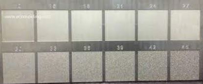
Are you looking for different mold texturing surface finishs on a plastic part cavity side? Plastic parts not only benefit from designs that are pleasing to the eye, but they also benefit from the way a product feels when handled. Depending on the application, you may want your plastic mold part to be as smooth as glass or possess a rough feel to indicate strength and durability. One way to injection mold a molded part with a unique look with different grain on the part surface, which we call mold texture surface finish.

Mold texturing

What is Mold Texturing surface finish?

Mold Texturing surface is a process used to apply patterns to the mold cavity surface. This process allows flexibility in creating the final appearance of your parts. Mould Texturing finish is an integral piece in overall product development and should be considered during the design process to achieve the desired results. Mold Texture can be a functional component of design as well.  Some surface issue on molding part can be covered by the right texture. Is the part designed for frequent handling? Texture finish can be used to hide finger prints and improve the grip for the end user. Surface Texture can also be used to reduce part wear from friction.

Some important considerations to keep in mind when you plan to add texture surface finish on your plastic molded part

  • Which surface do you need to add texture finish? normally texture finish will go to the outside surface
  • what plastics will use for your plastic molding part? Thermosets, Ryanite, Glass Filled Nylon, Glass Filled Polypropylene, ABS, Polycarbonate, etc. different plastics material will usually require different draft for same texture finish.
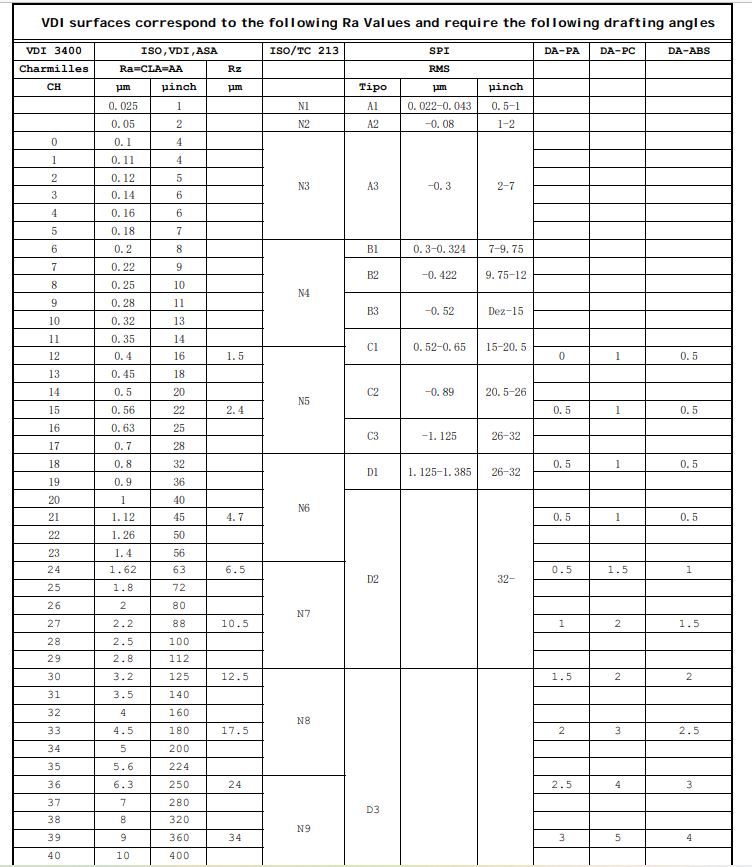
  • What grade /type of texture finish do you need? on the market the most use of surfaces are VDI 3400 texture, leather texture, wood texture, etc., each type of texture has different grade of texture finish as well, for example VDI 3400 texture finished that has grade texture finish from VDI 12 to VDI 45, different grade of VDI texture requires different of draft angle.

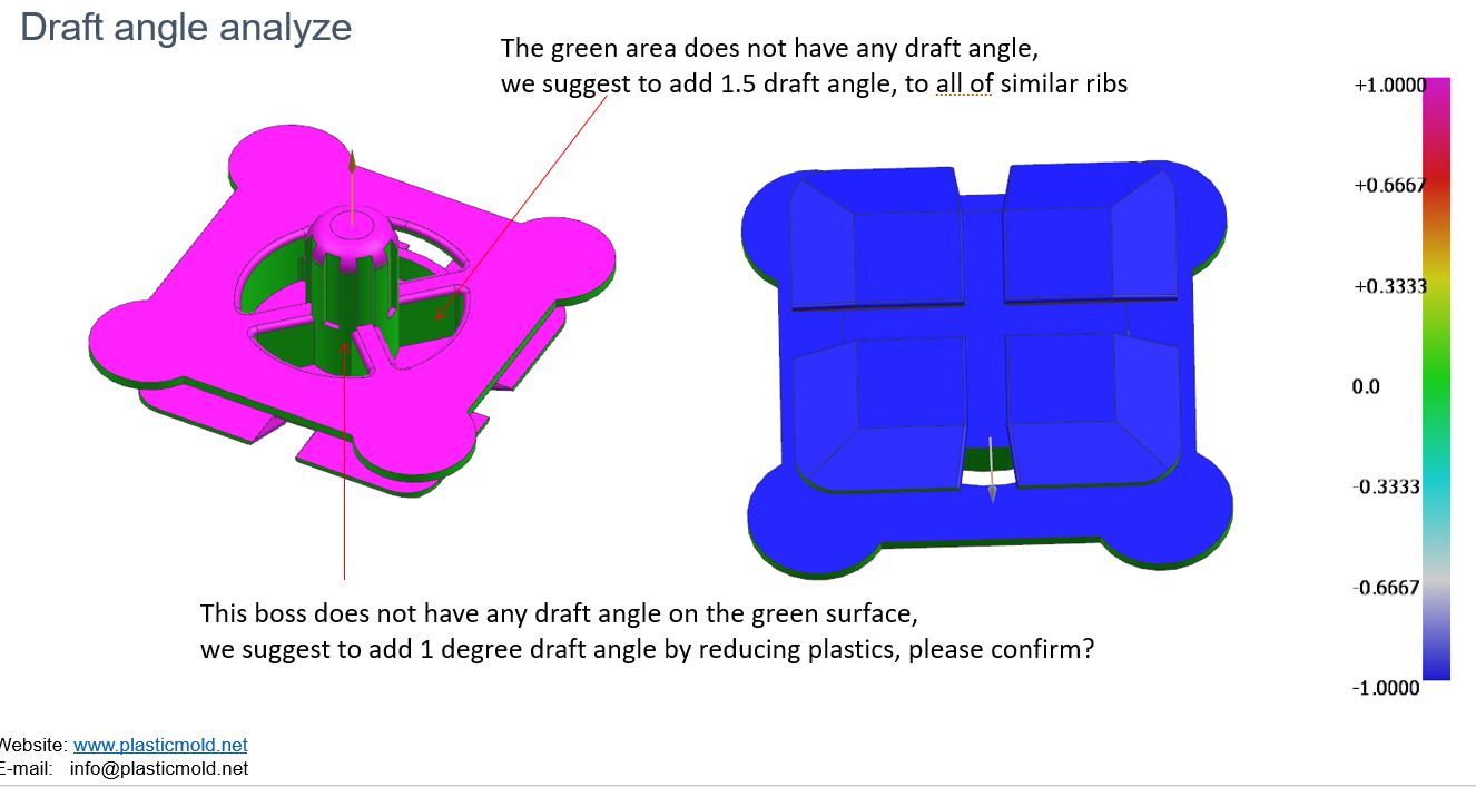
In order to facilitate the removal of the finished product, there must be an appropriate draft angle in the ejection direction of the finished product; for finished products that do not bite, it is recommended to have at least 1°, and of course the larger the better.
For finished products with bite marks, depending on the type and depth of the bite marks, the angle should be at least 3~5° if possible.
VDI 3400 is Electric Discharge Pattern (EDM)
For VDI 3400, please refer to the table below: (Generally, it is better to add 1° to the angle)

Below is VDI3400 plastic surface finish chart

VDI3400Average depth

Ra(μm)

Maximum depth

μm

PC(Draft angle)ABS(Draft angle)PC/ABS(Draft angle)
120.401.501.000.501.00
150.562.401.000.501.00
180.803.301.000.501.00
211.124.701.000.501.00
241.606.501.501.001.50
272.2410.502.001.502.00
303.1512.502.002.002.00
334.5017.503.002.503.00
366.3024.004.003.004.00
399.0034.005.004.005.00
4212.5048.006.005.006.00
4518.0069.007.006.007.00


by above explaining about plastic molding texture surface finish I assume you may little confused, but no worries, we are professional on all of the mold texture surface finish  jobs, you only need to send us your part design and we will handle all of questions for you.

VDI 3400 surface

custom plastic injection molding

Soft Mold Low Volume Plastic injection molding

In line with the history of the branch, since 1999, completely different companies have been providing innovative soft mold low volume quantity injection moulding solutions to numerous high profile organizations throughout a variety of industries throughout all of the continents. Undoubtedly the addition of low volume injection moulding capabilities to the portfolio makes these establishments a complete one-stop store for quick product growth; providing options from next day concept models all through to soft mold low quantity plastic injection moulded components in actual engineering plastics.

In the first place, let’s discuss injection moulding process. Predominantly, in accordance with the floor end in addition to quantity necessities we select essentially the most applicable in addition to cheap material to produce the plastic mould from, which is mostly aluminium or pre-hardened steel which we call soft mold. Therefore, mould design is created to satisfy the exact benchmarks of your project.

In addition, conventional machining utilizing the newest Excessive Velocity Milling (HSM) and CNC spark erosion techniques. It means that the mould tool is polished in addition to might be textured utilizing acid etching to create the desired surface finish. Moreover, detailed CMM inspections are carried out to guarantee that mouldigs are inside tolerance and of high quality. Last but not least, there’s submit processing of elements; including assembly, printing, portray in addition to chrome plating. All that is full mission managed by the companies.

low volume injection molding

You ought to perceive that there exist some advantages of low volume y injection molding. For instance, it requires low investment prices; short lead-times (from three weeks); needs as much as 10, 000 parts from a single mould soft steel; and components are available actual engineering plastics. Let us discuss them in more detail.

Perhaps allow us to start with the astonishing determine of as much as 10,000 parts from a single mould tool. Don’t forget that the mold will be designed to lessen costs whereas fulfilling your element’s visual, technical and amount needs. What’s extra, we guarantee that instruments are manufactured as cost effectively as possible, for instance, by designing a manual or automatic device depending on the quantity required.

We proceed to components are made in actual engineering plastics. This means your elements could be moulded in most engineering plastics, which enables the manufacture of parts which are suitable for most production environments.

You know that low funding prices in a mold instrument is a great advantage. By making a soft mold from aluminium, machining time and prices are low and the mold cavity of an aluminum tool may be polished quickly and cost effectively. What you will like concerning the offer is brief lead-times. Your mission can go from CAD & UG design to moulded parts in as little as 3 weeks. And you’ll reveal that there may be moreover environment friendly moulding of small batches. As there may be often no minimum order quantity, your low volume initiatives are all the time produced very cost effectively.

And to prime it, an experienced staff always provide a  custom-fit resolution, including over moulding to produce components containing a couple of material, for example a PC-ABS handle over molded with a TPE. Besides, over molding of electrical connections, inserts and steel plates with an engineering plastic can also be attainable.

General, soft mold low volume injection moulding is the ideal answer for low quantity manufacturing, bridging resolution in addition to pre-launch testing, we can offer you the low volume injection mold cost as low as $500, and this will be the best idea for you to open you market. if you have large quality parts, you could go to our high volume injection molding to know more.

Contact us to get a quote.

injection molding thick wall

How to save injection molding cost by Part thickness design reduction

By do the DFM (Design For Manufacturing) report and mold flow analysis to keep part thickness down to the minimum but having the same strength, we have reduced cooling times by as much as 31 seconds!  As you can see by the table below example to show you how much you could save your injection molding cost,  it doesn’t take a big annual volume for the savings to add up.

AttributeValue
Volume of Plastic Reduced.06  Lbs.
Cost / Pound of Plastic$ 5.34
Material Savings / part$ .32
Cycle Time Reduction15 seconds
Machine Cost / Hour$60
Production cost saved / part$.25
Annual Part Volume10,000
Total Annual Savings$5,700

Theory

It has been shown that cooling time averages about 50% of the molding cycle for a typical plastic molded part. The additional 50% of the time consists of the filling, packing, and part ejection phases, which do not vary significantly from mold to mold. The cooling phase is the only phase that has any degree of variability.  This is because the cooling of a molded part is determined by the rate of mold heat removal.  Heat removal is impacted by many factors. Factors include the melt temperature, cooling channels design,  part thickness, and the material and mold steel’s thermal capabilities.

Part Thickness design

Out of all the factors, the part wall thickness is the easiest to impact. In short, the thinner the part, the faster the cycle time, the more molded parts per hour get made. Since the relationship of part thickness to cooling time is exponential, a small thickness reduction yields big cooling time reductions and big savings.

As stated on the Injection Pressure page, part thickness reductions increase the injection pressure. The fundamental limit of how thin you can make the part is the machines pressure capability assuming that the part will still meet design intent with a thinner wall.

Without the use of mold flow analysis the part thickness is usually designed so that it errors on the thick “safe” side to avoid fill problems.  However, with mold flow analysis, the thickness of the part can be iteratively reduced until the pressure reaches safe level (typically 17,000 psi). The process is usually complimented by performing a stress analysis to verify that the thinner walled part still meets the products design intent.  The FEA process usually adds ribs and gussets  to preserve the strength while using thinner walls.

If We have any plastic project that is ready to start make the plastic mold and massive production, you are welcome to send us, we will check the part design issues for you and send you a price for your reference.

Plastic Part Design Analysis Theory

The plastic part molding process is heavily affected by factors of the plastic part design. If the critical parameters of a part design are not set correctly, the part will have quality issues during the molding process. The most critical of these parameters is as follows:

  • Plastic Part wall thickness
  • Part flow length
  • Thickness transitions
  • plastic Part material
  • Location of gates
  • Number of gates
  • Location of mold vents
  • Mold temperature
  • Melt temperature

A quick, cost effective mold flow analysis on a part design with the chosen material and gate locations can give an accurate prediction of how a part will mold before the tool is built. Verifying  that a part design will work with the given set of critical parameters is key. If the part does have quality issues, our analysis report will recommend ways to adjust the required parameters so that the problem is eliminated.

Plastic part design without the use of mold flow analysis forces the designer to use rules of thumb, guess at, or not consider these critical parameters.  This results in a high degree of risk that the part will not mold with acceptable quality levels.  Some times pushing processing conditions to the extreme limit will yield an “acceptable” part. 

However, this will cause high levels of molded in stress, degrade the material, increase scrap rates and/or increase cooling times.  Unfortunately, molds designed without the use of mold flow analysis have to resort to these tactics of “trouble shooting”.

Other critical data that is obtained by running a part design analysis includes:

  • Location of weld lines
  • Clamp tonnage requirements
  • Injection pressures
  • Location of high shear rates
  • Location of high shear stresses

How to prevent Sink Marks defects in advance

Sink marks defects are localized depressions in the surface of injection molded parts caused by a non uniform shrinking of the plastic during the cooling process. In cosmetically critical parts, they can be a serious problem. Sink marks are dependent on part geometry and material shrink rates. Sink marks often come as a surprise when the mold is complete.

If the sink marks defects are objectionable to the customer, the plastic mold manufacturer is often tasked with “eliminating them”. Since the mold is complete, the mold manufacturer does not have the luxury of changing the part geometry. At that point, changing the material to one with a lower shrink factor is usually not an option due to sizing issues with other parts.  At this stage of the game, the only option left to the mold company is to adjust the processing conditions to try to eliminate the sink. This usually means running the molding machine at the extremes of the process window, which can lengthen cycle times and increase the amount of molded in stresses.

Mostly, the best solution to solve the sink marks issue is reducing the wall thickness, since mold is made by the mold company, so will be high cost to solve this issue, to avoid this sink marks issue in advance will be the idea to prevent this issue, so mold flow analysis and DFM report (design for manufacturability) is the most important role to avoid this sink marks defects.

The part below was suffering sink marks defects beyond what was allowed by the part designer’s requirements. If the tool was built to this geometry, they would have had a serious problem. Looking at the graduated scale we can see a maximum of .004″ of sink.  It doesn’t sound like much, but .005″ is the limit on the print. To fix the issue, the two thick ribs on the underside of the part were reduced in thickness.

sink marks defects

sink marks defects


Mold Fill time is another name for melt front advancement. Our fill time animations provide the visualization of the part cavity filling before your very eyes!  As you can see from the animation, phenomena such as race tracking, weld lines formation and air trap formation are easy to visualize. Race tracking is when the plastic flow fills the thicker section of the parts prior to filling the thinner sections.  Race tracking moves the plastic in non intuitive ways which will trap air in the tool in places that are hard to vent.  The use of the melt front advancement tool solves these problems before the tool is built avoiding the quality problems in the part.

Melt front advancement is especially useful in our Gate Optimization Analysis. When trying several gate locations, the melt front advancement helps you visualize how the changes in gate position will change the way the cavity fills.  This allows you to position weld lines so that they are either in low stress or low visibility areas of the part.  Notice  that the weld lines (red lines in image below) are formed on the bolt side of the ports where the flow meets together as it comes around the port.  This was done to place them in a less visible location on the part.

Melt front advancement is also imperative when performing a Runner Balance analysis.  The critical requirement of a runner balance is to have all of the different sized cavities complete filling at the same time.  This creates a condition were all cavities receive the same packing pressure.  This prevents a short shot in the harder to fill cavities or over packing or sticking in the easy to fill cavities.